About our Project
Project Target
Two different objects get delivered by a conveyor belt and detected by a camera system. An image processing system recognizes the coordinates of the objects and which of the two gets delivered. Then they get divided on two other conveyors with the help of a delta robot that assumes the needed information from the image processing system. A six-axis-robot then puts the objects back to the first conveyor belt.
The whole system involving a six-axis robot, a delta robot, five conveyors, a camera and a visualization panel, coordinated by a programmable logic controller.
The targets of this project are to learn the handling with industrial robots and programmable logic controllers. Furthermore the capacity for teamwork and the feel for time planning should be improved.
Image Processing
The software used for image processing is Motopick, the camera is a Cognex. The Motopick software is compatible with the Motoman deltarobot. Patterns can be teached in to the software, which will then be recognised by the camera. The software then sends the position of the objects to the robot. The robot then counts the pulses of the conveyor belt and picks the object up when it is under the robot.
Robots
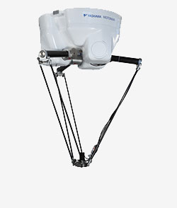
Yaskawa MPP3
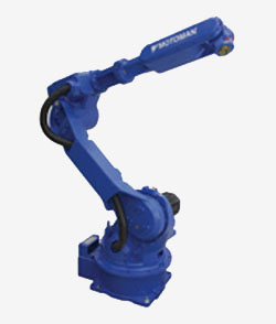
Yaskawa HP20D
The robots which are used are a Yaskawa MPP3 deltarobot and a Yaskawa HP20D 6-axis robot. The deltarobot gets the object position of the image processing system. It gets also the movement speed of the conveyor belt. With this data he can exactly pickup the objects from the first conveyor belt and sorts them to the second and third conveyor belt. The objects are delivered to the 6-axis robot via the forth and fifth conveyor belt. The 6-axis robot puts the back to the first conveyor belt, so there is a closed circuit.
The robots are programmed via a teach panel.
PLC System
The used PLC is a Beckhoff which is connected via EtherCAT to a Servocontroller. There is also a Profibus network involving two Beckhoff fieldbus slave, a Siemens fieldbus slave an two frequency converters.
The task of the plc program is to control the conveyor belts and robots. The inputs are buttons on the switching cabinet and the visualization. The buttons are wired to a fieldbus slave. The conveyor belts are controlled via the servo controller and the frequency converters.
Visualization
The Visualisation runs on a Backhoff touch panel. The panel is connected to the plc via EtherCAT.
The visualisation is made with the program Zenon Editor 7. It consists of pictures, functions and patterns. The patterns define the size and position of the pictures. The pictures are the screens of the visualisation. The functions can be used to switch between the pictures. You can connect variables of the visualisation with variables on the plc.
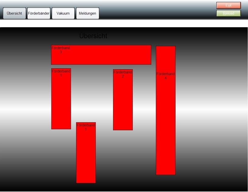
The Visualization consists of several different screens. The main screen is the overview. There you can see the status of all the conveyer belts and light barriers. The conveyer belts are red if they are turned off and green if they are turned on. If you click on a conveyer belt you will get forwarded to the screen of this conveyer belt. On the conveyer belt screen you can adjust the ramp and speed. You can also see the current speed of the conveyer belt and turn it on and off. There is also a vacuum screen to manually control the vacuum of the 4-axis robot (on and off). There will also be a screen for the error reports. You will see the errors and you have a button for acknowledge.